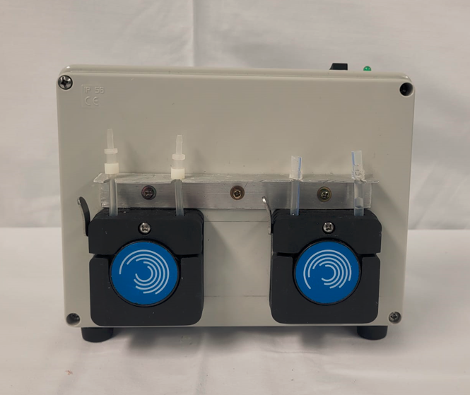
The peristaltic unit is a system made of two peristaltic pumps driven by two 42-step stepper motors, powered at 12v DC and controlled by two Easy-Driver boards.
Each Easy-Driver boards receive from the control unit a 0-5v logic signal for motor enable, a 0-5v logic signal for the direction of rotation, and a 0-5v square wave signal with duty-cycle 50% and frequency 10-5000Hz for rotational speed control.
The perfusion unit features a 12v fan for cooling the motors and boards.
The 12v power supply and signals from the control unit are transmitted through an Ethernet cable with RJ45 connectors.
Tubes within the pump compartment has been sized to achieve a flow rate of 0-50 ml/min for portal perfusion and 0-15 ml/min for arterial perfusion.


This is one of the most important parts of the system.
In previous versions I used DC motors for the peristaltic pumps: they were easily controlled by PWM signals from the Arduino board, but the actual flow showed a nonlinear correlation with the PWM values and it was also highly affected by the downstream resistance.
Stepper motors are characterized by a much greater torque force resulting in a linear correlation without significant effect by the downstream resistance. However, their control is more tricky and after some trials, I used the EasyDriver boards.
The rotational speed is proportional to the frequency (range 10-5000Hz) of 50% of duty-cycle signals directed to the EasyDriver boards. Since I was not able to produce two independent signals from a single Arduino board I solved the problem by sending two independent PWM signals to two Arduino-nano boards that can produce a 50% duty cycle frequency ( by the tone() function) proportional to the PWM value (using the pulseIn() function).
Probably this is not the best solution, but it worked and I am still using this configuration.


Crea il tuo sito web con Webador